Gate valves are the most common type of valve used for isolation. The valve consists of a main body section and bonnet, inside which a valve disc travels up or down the spindle by means of a disc nut. Convention is that when the spindle is turned clock-wise the disc will close and when the spindle is turned in an anti-clockwise direction, the disc will open. The sealing is made by contact between the metallic seats on the disc contacting with the metallic seats on the body.
Metal seated gate valves are used in both clean water and dirty water and sewage applications – but consideration should be given to the materials of construction for each application.
One of the main advantages of using gate valves for isolation is that the valve disc rises fully inside the body when the valve is open – thus giving a clear pathway for the medium inside the pipeline. This means the pipeline can be easily cleaned during pipeline maintenance procedures such as pigging. Another important advantage of gate valves is that because the disc is completely lifted out of the flow, the head loss (pressure drop) across the valve is minimal – so the pumping efficiency is increased and power costs are reduced, this can give considerable savings over the lifetime of the pipeline. The fact that the disc is lifted completely out of the pipeline flow is particularly important for dirty water and sewage applications – because there is less chance of debris getting blocked or snagging with the valve, which can happen with with other valves where the shaft or spindle is in the pipeline flow – such as butterfly valves etc.
Also metallic seating is advantageous in dirty water and sewage applications in that it is more robust and less susceptible to damage compared to soft rubber /resilient seated valves.
The disc and body seats have a tapered design so that contact between the seats occurs only when the disc reaches the closed sealing position. This means that the wear on the disc seats is reduced and gives longevity to the valve.
Gate valves are designed for isolation (on-off duty) operation and are not to be used for regulation or throttling purposes. Gate valves are used for directing the flow of the pipeline, and are ideal for positioning either side of special pipeline equipment – pumps, flow meters, PRV’s, strainers, filters, air valves etc – so that these items can easily be isolated for maintenance or replacement purposes.
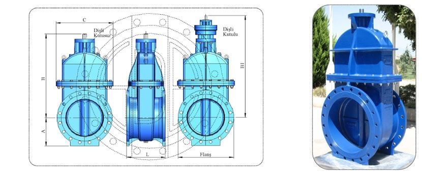
Gate valves are typically manufactured as Non-Rising spindle type, however certain special applications may require Rising Spindle design, whereby the spindle and disc are lifted out of the pipeline using a drive nut or (yoke) which positioned outside of the valve body.
Generally, gate valves should be positioned with the spindle in the vertical (upright) position, however, in situations such as vertical pipelines where the valve is positioned horizontally or when space prohibits the valve from being upright, and the valve is position off vertical or on its side, then the valve should be fitted with guides and slippers to assist with the smooth open/close operation of the disc into seating position and to minimise wear on the seat material.
Gate valves are normally fitted with a cap top or hand-wheel for manual operation, but for the larger sizes or for high pressure applications, it may be preferable to fit manual gearboxes or electric and hydraulic actuators to operate the valve. Spur gearboxes – are the more common standard design of gearbox which transfers the torque directly through to the valve spindle. Standard ratios of 4:1,8:1 and 16:1 are common. The input shaft – and therefore the cap top or hand-wheel of the gearbox remains in-line with the main valve spindle. Bevel gearboxes transfer the torque using a series of gears that gives rise to the input shaft of the gearbox being 90 Deg to the spindle of the valve. This is advantageous for the operation of gate valves in vertical pipeline – and bevel gearboxes are used as standard on rising spindle designs as the valve spindle has to rise up through the gearbox. Electric actuators – basically an electric operated gearbox – allowing the opening and closing of the valve from either a local or remote position.
The non-rising spindle gate valve is the most common form of gate valve – whereby the threaded section of the valve spindle is positioned inside the valve chamber. When the spindle is operated in an anti-clockwise direction, the wedge nut, which is located and fixed in the groove pocket of the valve disc, winds up the valve spindle, and this in turn, lifts the valve disc up into the upper body chamber and the valve becomes fully open. The valve disc and spindle are completely out of the way of the flow – thus providing minimum head loss and increasing pumping efficiency thereby reducing energy costs as the flow is relatively smooth through the valve. To close the valve, the direction of operation is changed to clockwise. Standard international convention is Clockwise Closing.
Metal seated gate valves can be used for clean water, dirty and waste water and screened sewage – but care should be taken to specify upgraded materials of construction – especially for the spindle, valve seats and bolts if aggressive chemicals are present.
Installation position : The valves should be installed whenever possible with the spindle in the vertical position. For horizontal installation, valves, especially in sizes above 300mm, should be equipped with guides and slippers to assist with the open/close operation and to reduce wear on the disc and body seats.
The valves are equipped with a drain plug at the underside – so that any sediment build up in the seating area can be easily drained and the larger valves above 300mm are also fitted with a vent plug as standard to evacuate any trapped air in the upper chamber of the valve body during the initial filling of the pipeline. Lifting eyes bolts are fitted to all large valves to assist installation and the valve flanges have flat bottom sections to allow easy storage of the valves.
The o-ring sealing system of gate valves is by far the most common and reliable form of stem sealing and has now pretty much replaced the old design of gland packing (stuffing box sealing) for non –rising spindle gate valves. The o-rings can be made of EPDM or NBR according to the application required. The o-ring stem sealing system energises as the valve becomes pressurised ensuring a water tight seal.
Over time and depending upon the environment in which the valve is operating, the seals may dry out and wear – however with this design – the o-ring seals can be quickly and easily changed whilst the valve is under pressure and in the fully open position, so that the o-ring replacement can be carried out without interrupting the flow inside the pipeline.
The SDE metal seated gate valve is designed with an ISO flanged top connection as standard – so that for the larger valves where gearboxes or actuators are to be fitted – the connection is made relatively easily.
For enhanced corrosion protection – all SDE valves are coated using Fusion Bonded Epoxy (FBE) powder coating – which is spray applied to the casting components. This ensures that all SDE valves have a typical coating protection of 300microns to give increased corrosion protection in harsh environments. WRAS approved coatings are used so that valves are suitable for potable water applications.
Gate Valves are ISOLATION valves – and are designed to be either in the fully open or closed position. These are not regulating valves for flow control and should not be used as such, but only used for ISOLATION purposes.
Available Accessories
Hand-Wheel : The most common accessory – which is a wheel used to open and close the valve manually.
Cap-Top : The Cap top follows a standard dimension and is to allow the valve to be operated using a T-key.
By-Pass Arrangement : The By-pass is as the name implies – a bypass arrangement around the valve – that connect the two chambers of the valve either side of the valve disc. The by-pass arrangement includes a small gate valve which can be used to open and close the by-pass. By-Pass arrangements are very useful for large size manual operated valves usually over 600mm diameter or when with high pressure applications. Higher torques are needed to open larger valves or when there is a large differential pressure across the disc, and this high torque is needed to break the seal between the valve seats. (Cracking open) With a large differential pressure across the disc, the forces act in one direction to push the valve disc into the body seat and as such the force required to open the disc is increased considerably. This can also increases wear on the valve seats when the valve is opened. This torque however, can be considerably reduced by the use of the bypass valve. Upon opening of the by-pass valve – the pressure difference across the valve reduces – and this makes the opening of the valve much easier as the disc becomes more balanced in the valve body. Larger valves that would need a high ratio gearbox can be fitted with a by-pass and then it may be possible to operate without the need for gearbox or perhaps a smaller ratio gearbox – thereby reducing the number of turns to open or close the valve. The By-pass can also be used to transfer the fluid from the outlet side to inlet side – so if the pump chamber is empty, by opening the by-pass valve, the fluid can be transferred into the pump chamber to initiate pump operation. By-pass is applied for valves comply with EN558-1 S19 (BS5163 Long pattern) and S15 face-to-face standard.
Headstock or Pillar : This can be used to support the longer extension spindles and can facilitate the attachment of a gearbox or actuator that may be positioned at a different level to the valve. For example if the valve is installed on the first floor and it is to be operated by a gearbox and handwheel from the second floor, the extension spindle extends the valve shaft upto the second floor and is supported using guide brackets and terminates at the top of the headstock or pillar. The gearbox can be connected to the spindle and bolted to the Pillar or headstock which will usually have an ISO mounting flange at the top.
Chain Wheels : Chain wheels can be installed if the valve is installed at a high point and access is difficult to operate the valve. The chain wheel is then more practical to use compared to a standard hand wheel. A chain is used to operate the valve from below.
Guides and Slippers : These are used to achieve a smoother disc travel and give longer valve life. Guides on body are usually made of stainless steel and the slippers on disc are made of bronze. These are strongly recommended for valves which are not installed in the upright vertical position.
Jacking Screw : This is located at the bottom of the valve body. It is a mechanism used to move the disc upwards if there is a sticking problem. It is not a common requirement but it can be supplied upon request.
Mechanical Indicator : This is a simple addition to the gate valve and should be specified at time of order. It is simply a mechanical adaption to the top works of the valve which shows the position of the disc inside the gate valve which is not visible once the valve has been installed. The spindle of the gate valve is extended and the top section is fine threaded, so that as the spindle is rotated – the indicator arm winds up and down – to show the position of disc during open-close.
Indicator with Switch : Basically this is just an adaption of the mechanical indicator but has limit switches set at the open and closed position- which trigger a signal that can relay to a distant control panel to indicate.
Planet Spur Gearbox : For large valve or where there can be high differential pressures across the valve disc, such as end of line applications, washouts etc, the torque needed to open close the valve is increased – which makes it difficult to manually operate the valve without some mechanical assistance. For Non Rising Gate Valves – the most common method is the addition of the Spur gearbox. With a spur gearbox, the input shaft of the gearbox is in line with the valve spindle SDE’s own planet spur gearbox is a compact and robust design offering good mechanical advantage to operate the valve. Ratios of 4:1 8:1 and 16:1 are typical – and make the operation of the valves much easier by simply reducing the input toque needed to operate the valve. The gearbox is simply positioned over the valve stem and bolted to the ISO Top flange.
Bevel Gearbox : This works exactly just like the spur gearbox – however the input shaft of the gearbox is at 90 Deg to the valve spindle. These gearboxes are normally are used on Rising-Spindle gate valves, where by the spindle rises up through the valve and gearbox but bevel gearboxes are also very useful for when gate valves are installed in the horizontal position, for example in a vertical pipeline. This way, the valve can still be operated from a position above the valve.
Actuators : Electric or Hydraulic actuators can be simply fitted to the Non-Rising gate valve – in a way similar to the gearboxes. The standard ISO top connection allows easy bolting of the device to the valve. The drive bush of the actuator is machined out so that it fits over the valve shaft and key way – so that it is locked into position with the valve spindle – and when the actuator flange is bolted to the valve ISO Flange – the actuator when powered – will drive the valve open or closed.